Inspect & power on
Verify grounding, connect approved power, switch on, and confirm cooling fan operation.

Model-specific service guidance for verified owners of the AM-275 induction sealer. Sign in to access quick-start instructions, operating procedures, diagnostics, and service resources.
Registration is activated only after confirmation of an authorized AM-275 serial number.
Get the current guide, operating procedures, and technical reference for your equipment.
Clear, durable support information when your operation needs it.
Use your equipment-linked account to continue.
Authorized service documentation, safety guidance, configuration references, and daily operation support for the AM-275 electromagnetic induction cap sealing system.
Front, side, sealing-wand, and control-panel imagery will appear here when supplied.
Use this concise sequence to set up, calibrate, and inspect your first AM-275 seal. Video timestamps will be inserted after source footage is received.
Verify grounding, connect approved power, switch on, and confirm cooling fan operation.
Install the induction foil with foil-side facing the container lip; tighten the cap securely.
Start with the recommended parameter range for the closure diameter and liner construction.
Position the head level and concentric with the closure, then activate the trigger cycle.
Allow cooling, remove the cap, and confirm a full perimeter bond without scorching.
This space is prepared for the supplied operating video, including a player, timestamped milestones, and transcript-backed key instructions.
Use the AM-275 only as directed by trained personnel and with compatible non-metallic container systems.
Never operate on metal containers or caps with exterior metal shells. An induction field can create arcing, fire, or equipment damage.
Keep vents clear. Avoid contact with the head during operation and allow cooling between high-duty cycles. Follow manufacturer guidance for medical implants.
Use these placeholders as a starting framework; final settings will be verified against your AM-275 operating video and approved application data.
| Cap diameter | Bottle material | Liner construction | Recommended time | Power level | Expected outcome |
|---|---|---|---|---|---|
| 20–35 mm | HDPE / PP | Paper / pulp-backed foil | 0.6–0.9 s | 3–4 | Full circumferential peel seal |
| 35–60 mm | PET / PE | Foam-backed foil | 1.0–1.4 s | 4–5 | Clean hermetic bond |
| 60–90 mm | HDPE / treated glass | Glass / foil liner | 1.4–2.0 s | 5–6 | Tamper-evident barrier |
| 90–120 mm | HDPE / PP jar | Universal induction foil | 2.0–2.8 s | 6–8 | Full perimeter adhesion |
Apply this pre-operation and quality-control checklist at every AM-275 installation and production start-up.
Commission the equipment in a dry, stable, serviceable work area.
Confirm seal integrity before releasing a production run.
Browse factory-engineered bolt-on options, quality detectors, and OEM replacement parts for your registered AM-275 sealing system.
Download verified binary images for the AM-275 Touchscreen HMI and Inverter Power Board, complete with safety procedures.
| Version | Release Date | Status | Target Hardware | Notes & Changelog | Action |
|---|
| Version | Release Date | Status | Target Hardware | Notes & Changelog | Action |
|---|
Follow these 5 verified steps to update the AM-275 Smart Seal Touchscreen HMI using an SD/SDHC card. Illustrated directly from factory service footage.
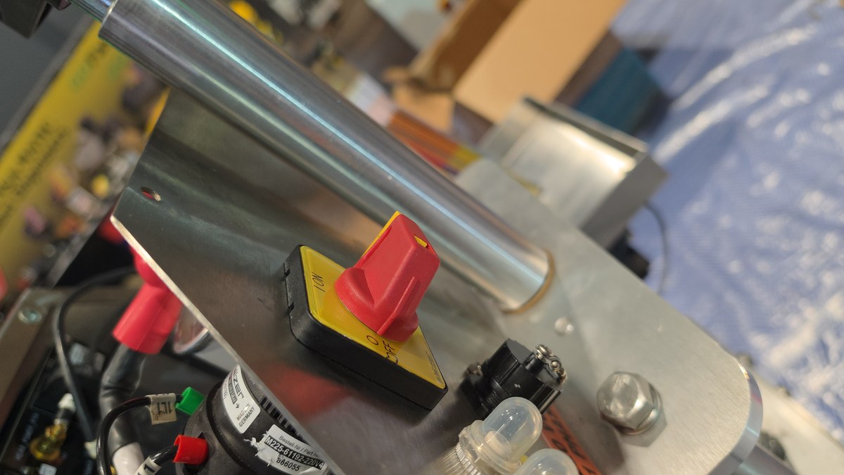 STEP 01
Locate the main yellow/red rotary disconnect switch on the AM-275 side column. Rotate the switch to the OFF (0) position and verify the touchscreen is no longer powered before accessing the HMI controller.
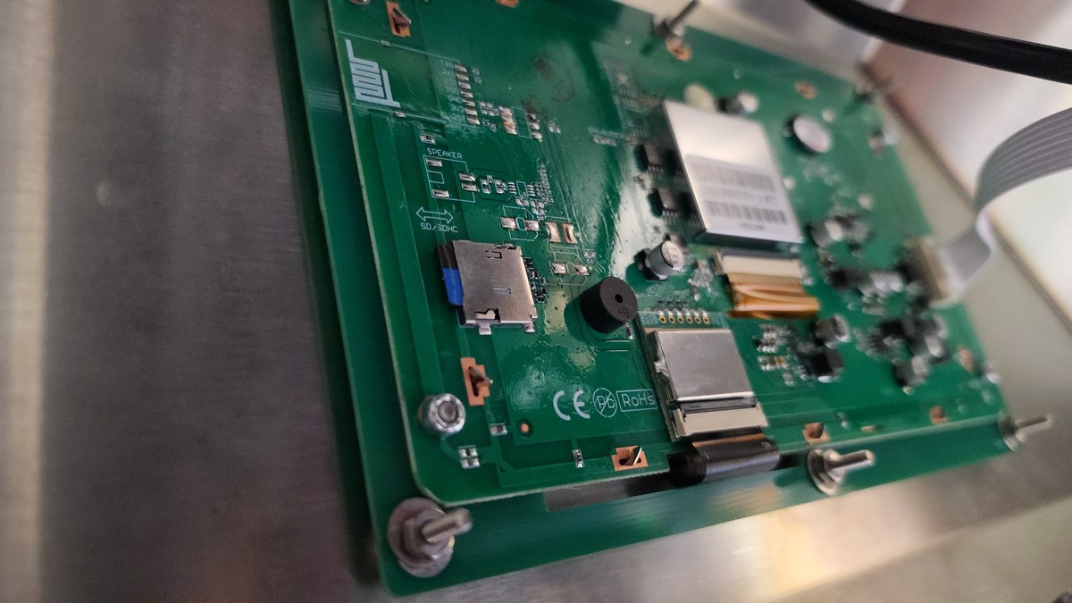 STEP 02
Access the rear of the Smart Seal touchscreen panel. Locate the onboard SD / SDHC slot, shown beside the ribbon connector and piezo beeper. Insert the prepared firmware SD card firmly into the slot.
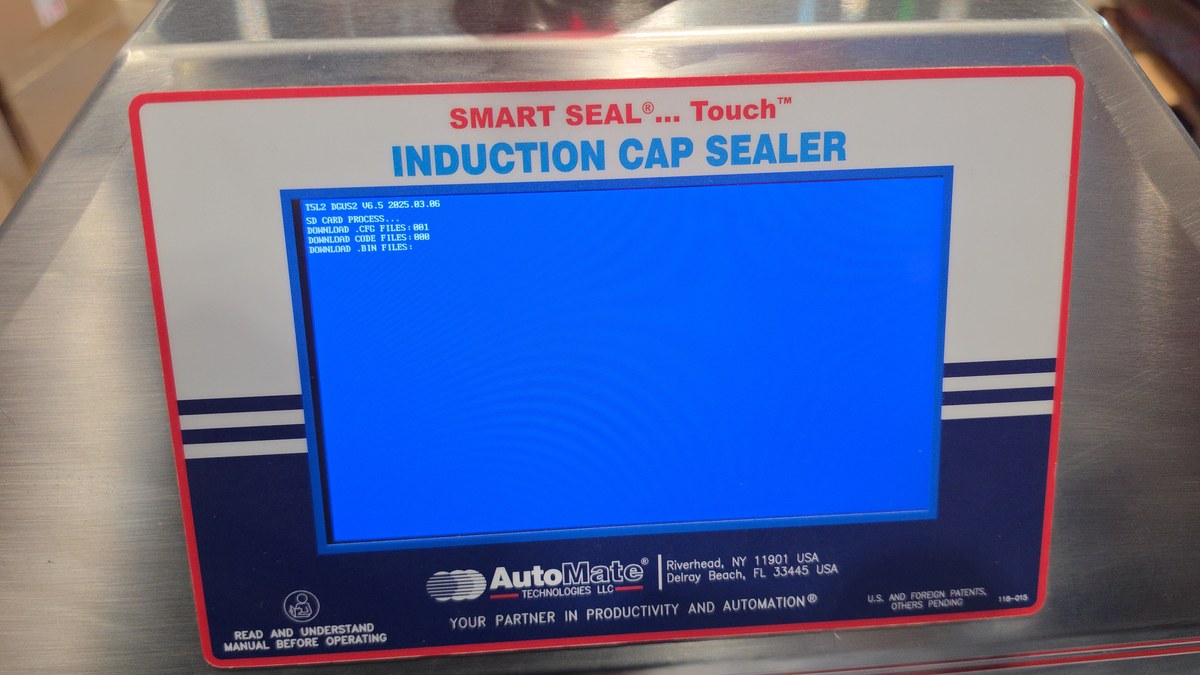 STEP 03
Rotate the main rotary disconnect switch back to the ON (I) position. The AM-275 Smart Seal Touchscreen powers up into the bright blue DGUS process screen shown here and begins reading the SD card.
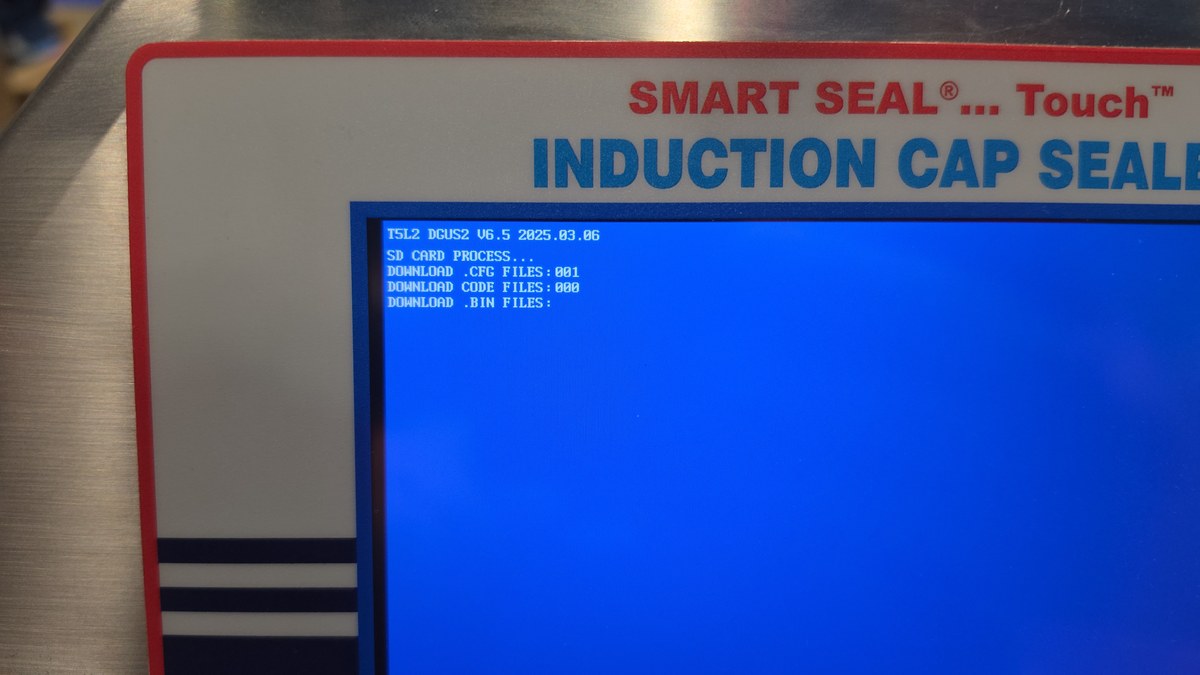 STEP 04
The bootloader screen displays the controller kernel version (T5L2 DGUS2 V6.5) and sequential download counters for:
• .CFG FILES (Display configurations)
• .BIN / .DZK FILES (Fonts, graphics, and system binaries)
• .ICL FILES (UI icon and screen image libraries)
Allow all packages to transfer until the progress counter reaches completion.
.CFG, .CODE, .BIN, .DZK, and .ICL. Do not interrupt the process while counters are updating.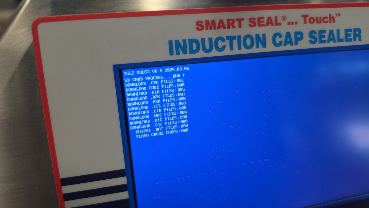 STEP 05
When the screen shows SD CARD PROCESS ... END ! and the displayed FLASH CRC32 CHECK is complete, the visible update cycle has finished. Power the machine OFF, remove the SD card, then power it back ON for a normal HMI startup.
Staged for the primary walkthrough video (Part 1 - long overview) and quick-flash clip (Part 2 - short summary). A dedicated Power Board flashing guide will be appended beneath once the second demonstration video is uploaded.
Use the likely causes and immediate corrective actions below to return your line to a valid seal condition.
Protect long-term reliability with basic inspection, cleaning, and ventilation care.

Use the QR code to open the web address on a mobile device. The code resolves to the planned customer portal address and will work as soon as am-275.com is registered and routed to this project.
https://am-275.com